간단 사양::
High Voltage Analog Inputs 4개 채널의 고전압 전용 아날로그 입력 (+/- 10V, 12-bit 해상도) 해상도 설정 변경 가능 Flexible I/O 8개 채널의 변경 가능한 저전압 아날로그 입력 (0~2.5V, 12-bit 해상도) 혹은 디지탈 Input/Output 채널로 설정할 수 있는 채널. Digital I/O 8개 채널의 디지탈 Input/Output 전용 (EIO4-EIO7 and CIO0-CIO3)
Analog Outputs 2개 채널의 아날로그 출력 (10-bit, 0-5 volts) LJTick-DAC 모듈을 연결하여 아날로그 채널을 추가 할 수 있습니다.
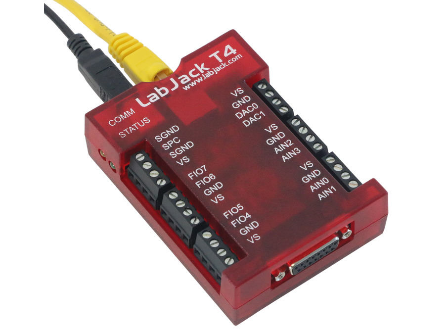
Hardware (상세 사양):High Voltage Analog InputsThe first 4 I/O lines on the LabJack T4 are dedicated high voltage analog inputs. Their voltage range is ±10V with 12 bits of resolution. For more details, look in the T4 datasheet. Flexible I/O:The 8 I/O lines marked as FIO4-FIO7 and EIO0-EIO3 are flexible I/O lines. This means they can be individually configured as digital input, digital output, or analog input lines. When configured as digital I/O, they can be used as general purpose 3.3V logic lines, can be configured for the timers/counters sub-system, or can be used as SPI, I2C, or other digital communication protocol lines. When configured as analog inputs, they are 0-2.5V analog inputs with up to 12 bits of resolution. Digital I/O:The T4 has 8 dedicated digital I/O lines marked as EIO4-EIO7 and CIO0-CIO3. These lines can be configured as general purpose 3.3V logic lines, as timers/counters, or as SPI, I2C, or other digital communication protocol lines. Analog Outputs:The LabJack T4 has 2 analog outputs (DAC0 and DAC1). Each analog output can be set between 0 and 5V with 10 bits of resolution. Timers:The T4 has multiple hardware timers that provide options such as PWM output, pulse/period timing, pulse counting, and quadrature input. Counters:The T4 has multiple hardware counters that can be used for detecting pin toggles. SPI, I2C, and asynchronous serial protocols 를 지원합니다./board/view?id=board3&page=0&seq=944 << I2C 관련 간단 설명
옵션 설명::
http://ezdaq.com/goods/catalog?code=000301570003 <<신호변환 옵션 관련
http://ezdaq.com/goods/catalog?code=000301570002 << 온도센서 옵션 관련
http://ezdaq.com/goods/catalog?page=2&code=000301570001 << 확장보드 옵션 관련
http://ezdaq.com/goods/view?no=515 << 모션 옵션 관련
/board/view?id=board3&page=40&seq=900 << U6-Pro 관련 (T-type TC 사용 실험 결과 포함)
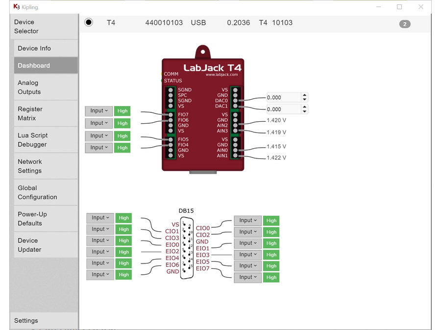
제조사 제공 LJ Kipling 소프트웨어 화면
|
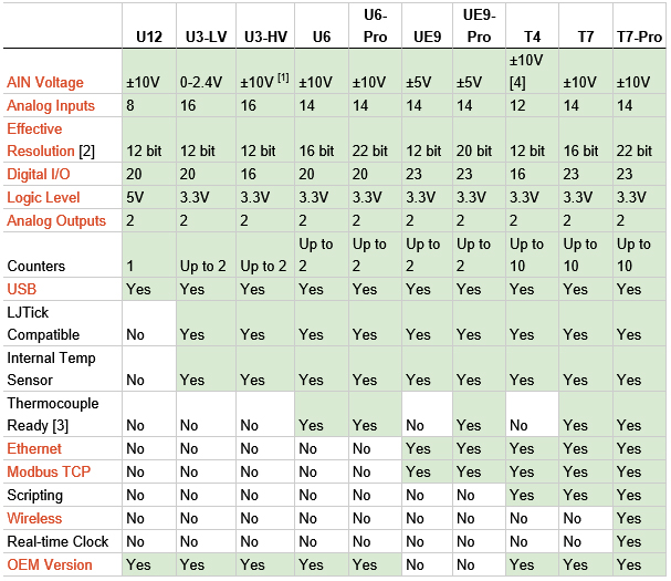
Labjack 제품 비교표 출처 http://labjack.com/products/comparison
T4 Quickstart Overview
1. Install the appropriate LabJack driver and software bundle.
2. Connect the T4 to the computer or hub through USB.

The status LED should blink at power up and then stay solid on
to indicate successful enumeration. If Windows asks about installing new hardware accept the defaults. If the device does not enumerate see item F on the USB Communication Failure App Note.3. Run Kipling.
 Kipling
 is a free application installed along with the driver. You should be able to find it in the Start Menu links.
4. Click "Refresh Devices" if the desired connection is not listed.
5. Click the connection (e.g. "USB").
6. Navigate to the Dashboard.
7. Connect a jumper wire securely from DAC0 to AIN0. Note that for a guaranteed valid connection a conductor must be clamped in the screw-terminal, not just touching some part of the screw-terminal.

DAC stands for "Digital to Analog Converter", AIN stands for "Analog Input".
8. The dashboard will read the voltage level of AIN0.

Adjust the DAC0 analog output voltage, and you will see AIN0 follow DAC0 if the jumper wire is installed.
9. Connect one end of the jumper wire to GND, touching the other end inside the FIO3 terminal.

GND stands for Ground. Try connecting and disconnecting the FIO4 end of the jumper wire.
10. The dashboard will read the current state of the digital input.
Digital inputs have an internal weak pull-up resistor that holds them high when nothing is connected. When the GND wire is connected to FIO4, the digital input will change from logic level High to logic level Low.
11. Connect a jumper securely between FIO4 and DAC0.
12. On the dashboard select the drop-down menu next to FIO4 and select "Analog"

The FIO and EIO lines on the T4 can be configured as low voltage analog inputs.
13. Set DAC0 and see the result on FIO4
 The status LED should blink at power up and then stay solid on to indicate successful enumeration. If Windows asks about installing new hardware accept the defaults. If the device does not enumerate see item F on the USB Communication Failure App Note.
 Kipling is a free application installed along with the driver. You should be able to find it in the Start Menu links.


 DAC stands for "Digital to Analog Converter", AIN stands for "Analog Input".
 Adjust the DAC0 analog output voltage, and you will see AIN0 follow DAC0 if the jumper wire is installed.
 GND stands for Ground. Try connecting and disconnecting the FIO4 end of the jumper wire.
 The FIO and EIO lines on the T4 can be configured as low voltage analog inputs.